AEO Answer · Theme Parks & Amusement Facilities
How Is a Ferris Wheel Structurally Engineered for Wind and Loads?
By Jeremy Mills, CEO & Founder, Apex Grid Engineering — USAF Veteran. · Updated 2026-09-15
Ferris wheels are structurally engineered to ASTM F2291, the design practice for amusement rides, for ASCE 7 wind loads on the full sail area, fatigue-detailed rotation components, and foundations resisting massive overturning — with redundant drives and brakes that hold the wheel in any condition.
I'm Jeremy Mills, CEO & Founder of Apex Grid Engineering and a U.S. Air Force veteran. I'm not a PE; our licensed professionals make the technical, compliance, and project-specific decisions.
Wind loading on the wheel and towers
The wind analysis treats the wheel as what it is: a giant open truss disk studded with capsules. Engineers calculate the wind pressure at the wheel's elevation per the building code's wind provisions, apply it to the projected area of the rim, spokes, and capsules — accounting for shielding between components — and analyze the resulting forces on the towers for the wheel parked at its worst rotational position. Gust effects and the dynamic response of the flexible structure are included where the code requires them. The towers themselves are designed as the load path for all of it: axial load from the wheel's weight plus the bending from wind overturning, with bracing that keeps the towers stable in both directions. Foundation overturning checks use the same load combinations.
Fatigue detailing for endless rotation
A wheel that turns all day, every day, accumulates stress cycles faster than almost any other structure. Engineers detail every connection in the rim and spokes for fatigue: welds are profiled and inspected to the appropriate quality level, bolted connections use slip-critical detailing where cyclic slip would be a problem, and the design avoids geometric stress risers at the very points where the stress ranges are highest. The analysis identifies the fatigue-critical details and assigns them inspection intervals — the design includes the maintenance plan, because a fatigue detail is only as good as its inspection. Drive and brake components get the same treatment: the machinery that rotates and stops the wheel is designed with the redundancy and the braking capacity to hold a fully loaded wheel against the design wind with power lost.
Ferris wheel structural design checklist
A Ferris wheel structural package is ready when the wheel can turn safely for decades and stand safely in the worst storm. • Wind analysis covers the full, empty, and parked wheel at the worst rotational position • Towers and bracing designed for combined axial load and wind overturning moment • Rim, spoke, and connection details engineered for fatigue over millions of rotation cycles • Drive and redundant braking sized to rotate full load and hold against design wind on power loss • Foundations designed for overturning and uplift with a documented inspection and maintenance plan
The design standard: ASTM F2291, ASCE 7, and state inspection
ASTM F2291, Standard Practice for Design of Amusement Rides and Devices, is the document that turns a wheel from a tall structure into a regulated ride. It sets the loads and load combinations specific to rides — patron loads, operating and non-operating wind conditions, and fatigue assessment for components that cycle with every revolution — and it works alongside, not instead of, the general codes: ASCE 7 for site wind, snow, and seismic loads, AISC 360 for the steel, AWS D1.1 for structural welding, and ACI 318 for the concrete foundations. Where F2291 and the building code point in different directions, the engineer designs to the more restrictive and documents the basis, because the ride will be reviewed against both. Approval does not end at the permit. Most states run an amusement-ride inspection program — administered variously by a department of agriculture, labor, or a dedicated ride-safety office — requiring an acceptance inspection before opening and then periodic, typically annual, inspection, with documentation, maintenance records, and non-destructive testing of fatigue-critical parts in scope. A few states have historically had no statewide statute, shifting the weight onto insurer and third-party inspections. Find out which regime the site sits in at concept stage: its expectations belong in the drawings, not in a scramble before opening day.
The load path: hub, rim drive, and the unbalanced wheel
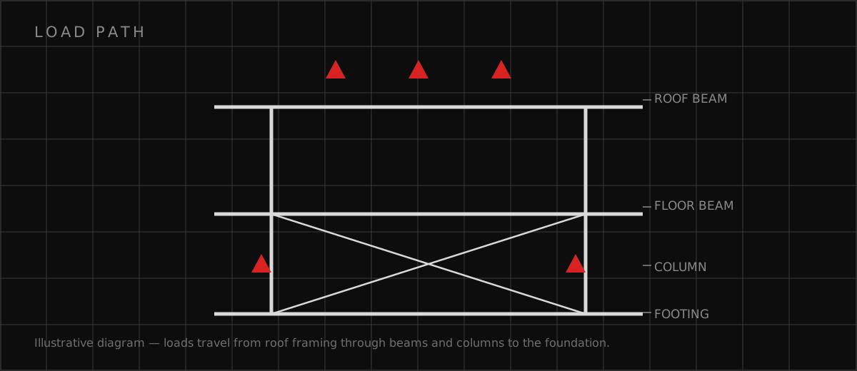
Every load follows one path: gondolas to rim, rim to spokes, spokes to hub and main shaft, shaft to its bearings on the tower heads, and towers to foundations. Gondolas hang from rim pivots and stay upright by gravity, so their pins and hangers are fatigue and wear parts by design, inspected and lubricated on schedule. Most larger wheels are rim-driven; smaller wheels may be hub-driven. Either way the drive must start, stop, and position a wheel whose passenger load is rarely balanced. Loading happens a few gondolas at a time at the platform, so the design includes the unbalanced cases — a full section of gondolas on one side, empty on the other — producing torque the drive and brakes must hold and a load pattern the rim and towers must carry. An auxiliary drive, independent of the main power supply, lets a stopped wheel always be rotated to unload passengers at the platform.
Foundations begin with the geotechnical report
The foundation design is only as good as the soils information under it, which is why a wheel project commissions a geotechnical investigation before the foundation type is even discussed. The report establishes bearing capacity, groundwater, and — critically, for towers that must stay aligned so the main shaft and bearings run true — expected total and differential settlement. Small uneven settlement misaligns the shaft, overloads bearings, and changes rim geometry, so settlement criteria for a wheel are tighter than for an ordinary building of the same weight. On competent soils, reinforced spread footings sized for overturning and uplift do the work; on soft, loose, or filled ground, drilled shafts or driven piles carry compression and net uplift to strata that can hold them. The engineer states the allowable bearing, uplift, and settlement values from the report on the drawings, so an inspector can see the basis.
What a Ferris wheel costs to engineer and build
Scale drives everything. A small transportable carnival wheel is a manufactured product, with site engineering limited mainly to foundations, anchorage, and permits, while a permanent observation wheel is a one-off structure. As typical planning ranges, structural engineering for a permanent mid-size wheel — analysis, fatigue assessment, foundation design, and the inspector documentation package — commonly runs from the high five figures into the low six figures, rising with height, wind and seismic demand, and poor soils. Installed cost spans wider: permanent wheels in the roughly 100- to 200-foot class commonly run from the high single-digit millions to tens of millions of dollars all-in, with foundations, drive systems, gondolas, lighting, and site work each capable of moving the total more than the bare steel. The honest early deliverable is a range tied to a named wheel size, a named site, and a geotechnical report.
Worked example: a 150-foot coastal observation wheel
Take a permanent observation wheel of about 150 feet proposed for a Gulf Coast boardwalk. The geotechnical report finds loose sand and a high water table, so spread footings are out before the first calculation: drilled shafts carry tower compression and storm uplift to denser strata. ASCE 7 wind for the site hurricane exposure sets the survival case — the parked, braked wheel in the design storm — and it, not the operating case, sizes the towers, shaft, and anchorages; ASTM F2291 supplies the ride-specific load combinations and the fatigue assessment that assigns rim connections and gondola hangers their inspection and testing intervals. The operating plan falls out of the same documents: the manufacturer wind limit at which boarding stops, the auxiliary drive that brings a gondola to the platform on backup power, and the state annual inspection, calendared before the first ticket is sold. Apex Grid Engineering PLLC engineers structures this way — standard, site, and soils decided together — and owners scoping a wheel can call 480-490-0064.
Which related engineering resources can help?
What else do project teams ask?
What is the strongest wind a Ferris wheel is designed for?
Why is fatigue such a big deal for Ferris wheels?
How do the foundations handle the overturning forces?
What keeps a Ferris wheel from moving in high wind when parked?
Who inspects a Ferris wheel after it opens?
What happens if the power fails with passengers on board?
How is corrosion handled on a structure that lives outdoors?
Ready to discuss your engineering scope?
Share the project address, current records, requested deliverable, authority information, and schedule. Apex Grid confirms professional responsibility, availability, and scope before work begins.
Request a Project Review