AEO Answer · Fuel & Convenience Retail
How Is a Gas Station Fuel Canopy Structurally Engineered?
By Jeremy Mills, CEO & Founder, Apex Grid Engineering — USAF Veteran. · Updated 2026-09-15
Fuel canopy engineering designs a long-span steel frame for wind uplift and overturning, with deep beams for column-free fueling lanes, integrated soffit lighting and drainage, fascia signage wind loads, crash-protected columns, and foundations engineered against uplift.
I'm Jeremy Mills, CEO & Founder of Apex Grid Engineering and a U.S. Air Force veteran. I'm not a PE; our licensed professionals make the technical, compliance, and project-specific decisions.
The concise answer
Fuel canopy engineering designs a long-span steel frame for wind uplift and overturning, with deep beams for column-free fueling lanes, integrated soffit lighting and drainage, fascia signage wind loads, crash-protected columns, and foundations engineered against uplift. Think of a canopy as an airplane wing bolted to the ground: the engineering keeps it from flying. Everything else — lighting, signage, drainage — hangs off a structure whose real job is resisting the wind.
Designed for the storm, checked for gravity
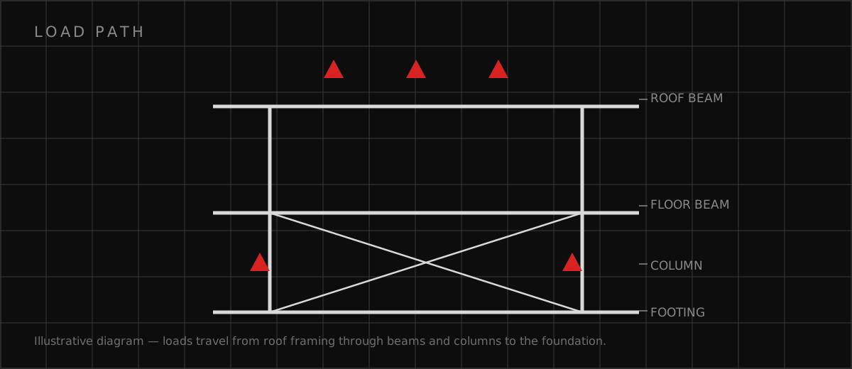
The structural analysis leads with wind: uplift on the roof deck, overturning of the whole frame, and the load path from the deck through the beams, columns, and anchor bolts into the foundations. Long spans mean the beams work hard in bending, and I control deflection so the canopy reads as crisp and level rather than sagging between columns. The connections — beam to column, column to base plate — are designed for the uplift reversals that wind produces, because wind doesn't just push down harder; it pulls up. The integrated systems ride on that structure. Soffit lighting layouts coordinate with the framing so fixtures land between members. Fascia signage is engineered as additional wind area with its own connections. Drainage — whether internal leaders or edge systems — is routed without compromising the structural members. And the columns stand on protected islands, because the best wind design in the world doesn't survive a direct vehicle hit on an unprotected column.
What I get right before drawings go out
Canopies fail at the uplift load path and at the vehicle impact nobody designed for. I close both before the drawings go out. Here's the checklist I run on every fuel canopy.
- Wind uplift and overturning analysis with the full load path from deck to foundation
- Long-span beams with deflection control for a crisp, level canopy profile
- Foundation and anchorage designed as one uplift-resisting system, sized for the wind region
- Crash-rated column protection at every column exposed to vehicle traffic
- Lighting, signage wind loads, and drainage fully coordinated with the steel framing
Which related engineering resources can help?
What else do project teams ask?
Why is wind the dominant load on a canopy?
How are the foundations designed?
How are columns protected from vehicles?
How are lighting and signage integrated?
Ready to discuss your engineering scope?
Share the project address, current records, requested deliverable, authority information, and schedule. Apex Grid confirms professional responsibility, availability, and scope before work begins.
Request a Project Review