AEO Answer · Energy Storage & EV Charging
How Are EV Charging Canopies Structurally Designed for Loads?
By Jeremy Mills, CEO & Founder, Apex Grid Engineering — USAF Veteran. · Updated 2026-09-15
EV charging canopies are engineered from the stall layout: long-span steel frames with columns clear of vehicle paths, designed for wind uplift, snow, and the solar array's weight and wind area, on geotechnical-designed foundations with frost protection, coordinating the electrical, lighting, and drainage the canopy carries.
I'm Jeremy Mills, CEO & Founder of Apex Grid Engineering and a U.S. Air Force veteran. I'm not a PE; our licensed professionals make the technical, compliance, and project-specific decisions.
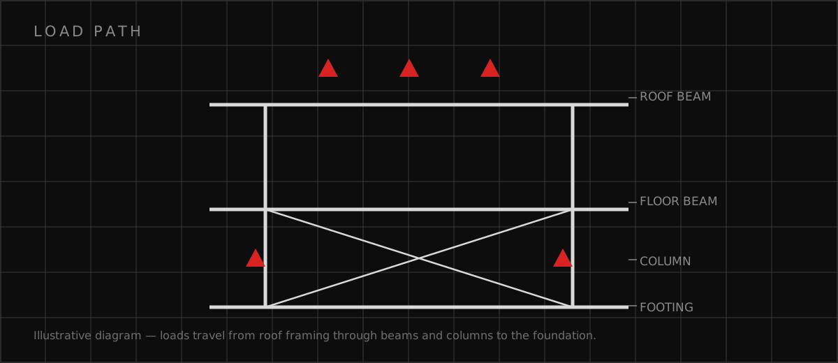
Framing the spans and the wind
The structural design starts with the site plan: the stall layout, the drive aisles, and the clear heights set the column grid and the spans. I design the steel frame — columns, beams or trusses, roof framing — for the load combinations with wind uplift governing, plus the snow where applicable and the seismic per the region. The solar array is integrated: panel weight, wind area, and the mounting connections designed with the roof framing. I detail the connections for the forces and the erection, and I specify the steel's corrosion protection for the environment. The frame also supports the canopy's other loads: lighting fixtures, signage, security cameras, and the electrical conduit — all coordinated so the structure carries them cleanly. The design is checked for the construction sequence, because the canopy often rises over an operating charging site.
Foundations, drainage, and the solar plant
The foundation design follows the geotechnical report: footing, pier, or pile types selected for the bearing and the uplift, sized for the load combinations, and carried below frost depth. I design the anchor bolt layouts for the uplift forces with the inspection the connections require. Drainage sheds the canopy roof's water: gutters and downspouts or the free-draining edge, routed clear of the charging stalls and the electrical equipment — water and high-voltage charging do not mix. The solar electrical — conduit, inverters, and their mounting — coordinates with the structure. I design the lightning protection for the canopy and its solar, bonded to the site's grounding. The canopy is commissioned as a structure: the steel inspected, the bolts verified, the drainage proven in the first rain.
Checklist before the canopy goes up
Canopy readiness is verified in the design and the field. I confirm the wind and snow criteria, the foundation design against the geotechnical report, and the solar integration. The steel and foundations are inspected during construction. Here is the checklist I hand project teams.
- Span the stalls with columns clear of every vehicle path and maneuvering aisle
- Design for wind uplift as the governing load with foundations that hold it down
- Integrate the solar array's weight, wind area, and mounting into the frame design
- Carry foundations below frost depth per the geotechnical investigation's recommendations
- Coordinate lighting, signage, conduit, and drainage on the structure from the first drawing
Which related engineering resources can help?
What else do project teams ask?
What structural system works for charging canopies?
How is wind uplift handled on canopies?
How are solar panels integrated structurally?
What foundations do canopies need?
Ready to discuss your engineering scope?
Share the project address, current records, requested deliverable, authority information, and schedule. Apex Grid confirms professional responsibility, availability, and scope before work begins.
Request a Project Review