AEO Answer · Mixed-Use Developments
How Are Structural Transfer Slabs in Mixed-Use Designed?
By Jeremy Mills, CEO & Founder, Apex Grid Engineering — USAF Veteran. · Updated 2026-09-15
A structural transfer slab is engineered as a deep, usually post-tensioned concrete plate designed for punching shear at every upper column, long-term deflection within finish tolerances, and simultaneous duty as the fire separation and lateral diaphragm between occupancies.
I'm Jeremy Mills, CEO & Founder of Apex Grid Engineering and a U.S. Air Force veteran. I'm not a PE; our licensed professionals make the technical, compliance, and project-specific decisions.
Punching Shear and Load Paths
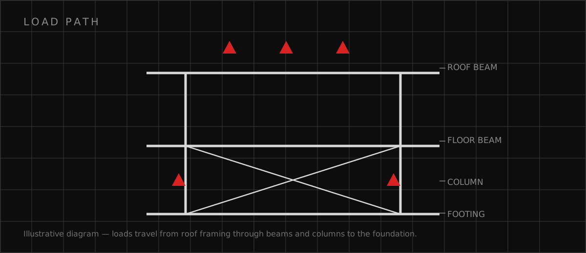
The engineer maps every load path before sizing anything: each residential column and bearing wall above, with its service-level and factored loads, plotted against the podium columns, walls, and foundations below that will receive them. The critical checks are the columns that land between supports — mid-span of the slab or midway between podium columns — where the slab must span the full distance carrying a point load. The punching-shear check runs at each such column with the slab's effective depth, the concrete strength, and the unbalanced moment the column delivers. Shear reinforcement is placed where the concrete alone is not enough. Headed shear studs arranged in rails around the column are the standard solution, designed per the code's punching-shear provisions with the stud layout shown on the drawings — spacing, extent, and number of rails per column. Drop panels are used where a cluster of columns or a wall landing needs a broader strengthened zone. The engineer also checks one-way shear on the slab strips spanning between podium supports and verifies that the podium columns and foundations below can accept the concentrated transfer loads, since the transfer slab only moves the problem down one level.
Post-Tensioning, Deflection, and Durability
The post-tensioning design balances a chosen fraction of the dead load — typically enough to keep the slab in net compression under service loads while leaving capacity for the live load. The engineer profiles the tendons in draped curves, high over the supports and low at midspan, and specifies the stressing sequence: tendons are stressed in a pattern that never lifts the slab off its supports or overloads the podium columns during construction. Elongation measurements during stressing are the field verification that the tendons are doing what the design assumed, and the engineer reviews the stressing records. Long-term deflection is computed with creep and shrinkage multipliers applied to the sustained load, and the engineer sets camber — a slight upward curve cast into the slab — so the finished surface lands level after the deflection occurs. Durability detailing matches the slab's importance: concrete cover per the exposure, crack-control reinforcement beyond the code minimum, and waterproofing at the top surface where the slab is also the podium roof. The engineer specifies the concrete mix for low shrinkage and reviews the curing plan, because a transfer slab that cracks early loses the stiffness the deflection design counted on.
Structural Transfer Slab Checklist
Use this checklist before the transfer slab design is issued: • Load map completed: every upper column and wall checked against receiving podium elements • Punching shear verified at each column landing, with stud rails or drop panels where needed • One-way shear and flexure checked on slab strips spanning between podium supports • Post-tensioning profile balanced for dead load, with a specified stressing sequence • Long-term deflection including creep and shrinkage within finish tolerances; camber set • Slab detailed as the rated horizontal separation with listed firestops at every penetration • Diaphragm shear, chords, and collectors designed for lateral transfer between systems • Hold-down embedments for the full residential overturning designed into the slab
Which related engineering resources can help?
What else do project teams ask?
How is a transfer slab different from a regular floor slab?
Why does concrete creep matter so much here?
Can you core through a transfer slab after construction?
What happens to the loads below the transfer slab?
Ready to discuss your engineering scope?
Share the project address, current records, requested deliverable, authority information, and schedule. Apex Grid confirms professional responsibility, availability, and scope before work begins.
Request a Project Review