AEO Answer · Solar Farms & Utility-Scale Solar
How Is Drainage Engineered Around and Beneath Solar Arrays?
By Jeremy Mills, CEO & Founder, Apex Grid Engineering — USAF Veteran. · Updated 2026-09-15
Solar farm drainage is engineered through the grading plan's sheet-flow slopes, swales and culverts that carry concentrated flows, raised equipment pads, and stabilized ground beneath panel drip lines — keeping water moving gently and away from foundations and equipment.
I'm Jeremy Mills, CEO & Founder of Apex Grid Engineering and a U.S. Air Force veteran. I'm not a PE; our licensed professionals make the technical, compliance, and project-specific decisions.
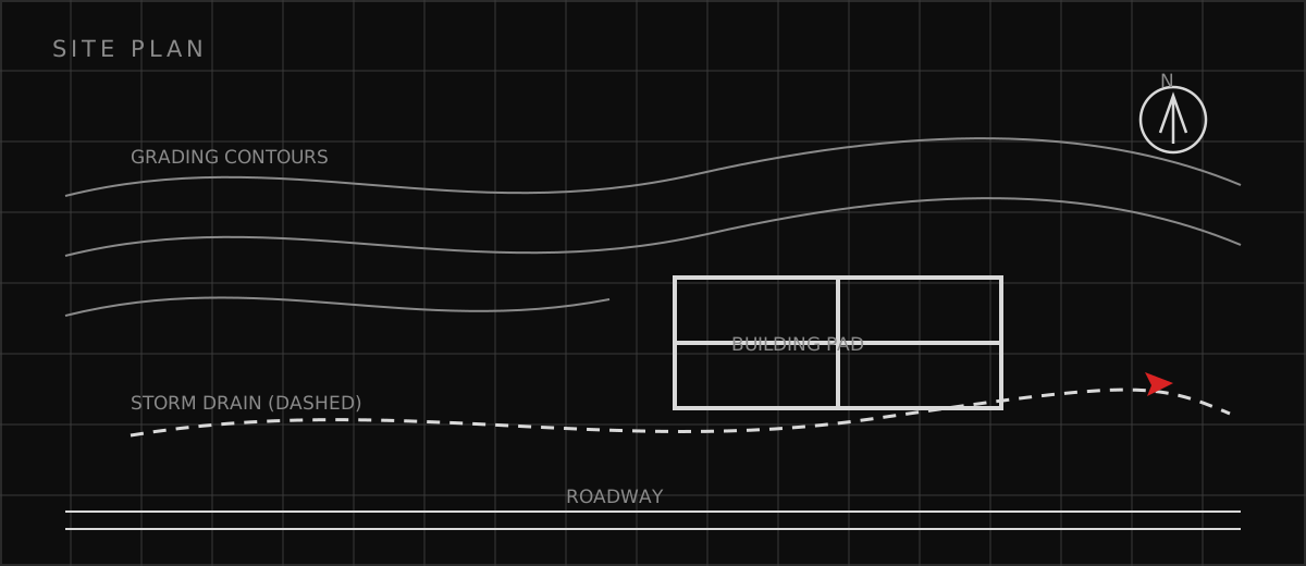
Grading for sheet flow
The grading design establishes the drainage pattern before a single swale is drawn: broad, gentle slopes that move sheet flow across and between the array blocks toward the collection points. I hold the slopes flat enough to keep velocities non-erosive but steep enough that water does not linger — typically a narrow band that satisfies both the tracker tolerances and the drainage needs. Finish grade elevations are coordinated with foundation embedment depths so the as-graded surface matches what the structural design assumed, and the grading plan notes the drainage intent so the earthwork contractor understands why the slopes matter.
Conveyance structures and crossings
Swales, ditches, and culverts handle what sheet flow cannot. I size each conveyance for its contributing area at the design storm, check velocities against the lining — vegetation, riprap, or reinforced turf — and detail inlets and outlets to prevent the erosion that starts at every transition. Culverts under roads get headwalls, aprons, and energy dissipation where the outlet discharges, and the design keeps conveyances clear of foundations and equipment pads. Maintenance access is drawn into the plan: a swale the mower cannot reach becomes a jungle that stops conveying.
Solar drainage design checklist
A drainage design is complete when it clears this checklist. On a solar site, drainage failures show up as erosion, corrosion, and flooded equipment — all preventable on paper. • Grading plan establishes positive sheet flow with no ponding under arrays • Finish grades coordinated with foundation embedment and tracker tolerances • Swales and culverts sized for design storms with non-erosive velocities • Equipment pads raised with positive drainage away from electrical gear • Drip-line zones stabilized against concentrated panel-edge runoff
Which related engineering resources can help?
What else do project teams ask?
Can water pond under solar panels?
How does grading affect drainage on a tracker site?
What protects solar foundations from water erosion?
How are access road crossings over drainage handled?
Ready to discuss your engineering scope?
Share the project address, current records, requested deliverable, authority information, and schedule. Apex Grid confirms professional responsibility, availability, and scope before work begins.
Request a Project Review