AEO Answer · Structural
How Are Steel Transmission Towers Designed for Wind and Ice?
By Jeremy Mills, CEO & Founder, Apex Grid Engineering — USAF Veteran. · Updated 2026-09-15
Transmission tower design engineers lattice steel structures for NESC wind, ice, and wire-tension loading cases, with bolted connections and foundations — drilled shafts, grillage, or rock anchors — matched to soil conditions. Tower geometry is set by electrical clearances and conductor swing first.
I'm Jeremy Mills, CEO & Founder of Apex Grid Engineering and a U.S. Air Force veteran. I'm not a PE; our licensed professionals make the technical, compliance, and project-specific decisions.
The concise answer
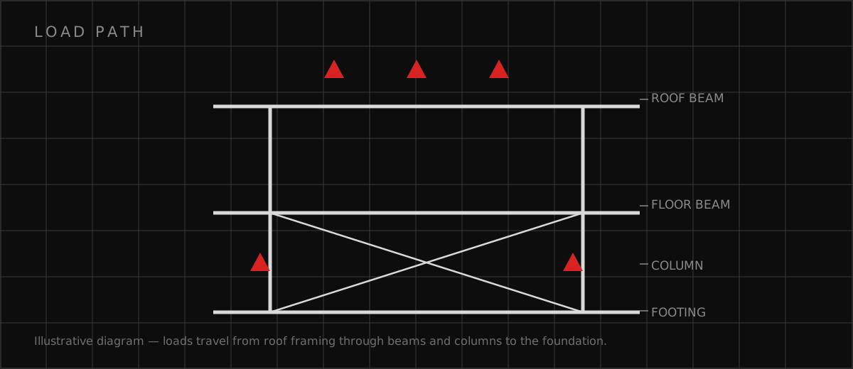
Transmission tower design is the structural engineering of lattice steel towers for high-voltage lines. It covers tower geometry set by electrical clearances and conductor swing, member and connection design for NESC wind, ice, and broken-wire loading, and foundation systems — drilled shafts, grillage, or rock anchors — proven against uplift. The tower is light, strong, and shippable in pieces; the engineering makes sure it stays standing through the worst weather on record for its route.
Foundations deserve the budget
Tower steel gets the attention, but foundations are where transmission projects win or lose money. Every tower site has different soil, and a foundation type that works at one site may be wrong at the next. Uplift usually controls the design, which surprises people who think of foundations as things that hold weight down. A proper geotechnical investigation along the route — not just at a few sample sites — is the cheapest insurance on the project, because discovering bad soil after the steel is ordered is how budgets die.
What the structural package covers
A complete tower design package typically includes:
- Tower geometry and member sizing for all NESC loading cases
- Bolted connection design for leg splices, arm attachments, and bracing
- Foundation design per site soil conditions with explicit uplift checks
- Conductor swing and clearance verification at extreme wind
- Climbing, fall-protection, and maintenance access provisions
- Corrosion protection: galvanizing specifications and coating systems
- Erection engineering: lift points, temporary bracing, and assembly sequence
Which related engineering resources can help?
What else do project teams ask?
What loads do transmission towers have to resist?
Why are most transmission towers lattice steel?
How are tower foundations selected?
What is conductor swing and why does it matter?
Ready to discuss your engineering scope?
Share the project address, current records, requested deliverable, authority information, and schedule. Apex Grid confirms professional responsibility, availability, and scope before work begins.
Request a Project Review