AEO Answer · Emerging Building Technologies
How Is Mass Timber Designed for Structural Loads?
By Jeremy Mills, CEO & Founder, Apex Grid Engineering — USAF Veteran. · Updated 2026-09-15
Mass timber structures are designed with CLT panels and glulam beams sized for gravity loads, lateral resistance through CLT shear walls or glulam frames, and connection details that force ductile steel yielding before brittle wood failure.
I'm Jeremy Mills, CEO & Founder of Apex Grid Engineering and a U.S. Air Force veteran. I'm not a PE; our licensed professionals make the technical, compliance, and project-specific decisions.
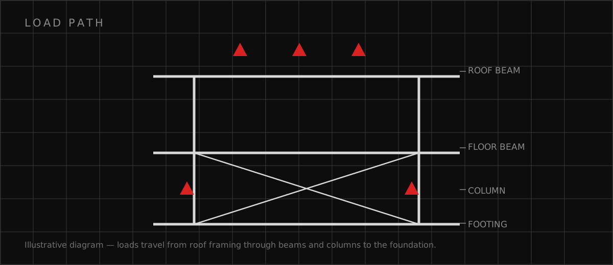
Gravity system design
I design the gravity frame from the panel up. CLT floor panels are orthotropic — strong along the outer lamella direction, weaker across it — so I orient the strong axis along the span and confirm the layup with the manufacturer's span tables before sizing anything else. Glulam beams pick up the panel reactions and run to glulam columns, and I keep the column grid tight enough that neither the panels nor the beams are working at heroic spans. Deflection almost always governs over strength: I check total-load and live-load deflection against the code limits, then check them again against the vibration criteria for the occupancy, because a floor that meets the deflection limit can still feel bouncy. Bearing design gets its own pass. Wood's compression strength perpendicular to grain is a fraction of its parallel-to-grain strength, so every beam seat, column base, and wall sill gets a bearing check with the right grain orientation. I use steel bearing plates, routed column caps, and where needed, reinforced bearing zones in the panel. Creep is real in timber: I apply the code's creep factors to long-term deflection and set camber in glulam beams where the dead-load sag would otherwise read as a defect in the finished floor.
Lateral systems and the connection hierarchy
For low- to mid-rise mass timber, CLT shear walls are the workhorse lateral system. Each wall panel is anchored at its base with hold-downs sized for the overturning tension and angle brackets sized for the story shear, and the panels are stitched to the floor diaphragm above with screws or straps that complete the load path. I treat every connection as part of a hierarchy: the ductile steel element yields first, the wood crushing modes are the second line of defense, and brittle modes like splitting or plug shear are designed to never occur. That hierarchy is what makes the building survivable in a major seismic event rather than just code-compliant on paper. In glulam post-and-beam buildings I design braced bays or moment-resisting frames, with the braces or beams connected through slotted-in steel knife plates and dowel or bolt groups. Diaphragms deserve the same rigor as the walls — CLT floor panels connected with spline joints and screws must actually deliver the story shears to the walls, so I design the diaphragm nailing and check chord forces. I also detail for shrinkage and settlement: cross-grain shrinkage accumulates over the building height, so hold-down rods get shrinkage-compensating devices and tall walls get tolerance in the connection slots.
Floor vibration and serviceability checklist
Mass timber floors are light, and light floors vibrate — so I treat footfall vibration as a primary design check, not a courtesy. The fundamental frequency, the damping, and the mass per unit area all feed the assessment, and I hold the design to published human-comfort criteria for the occupancy rather than to the code minimums, which say almost nothing about feel underfoot. • Size CLT panels for frequency and damping, not just strength and deflection — span-to-depth rules of thumb get checked against a real vibration calculation • Consider a concrete topping or screed where the occupancy is vibration-sensitive; the added mass is the cheapest damping a timber floor can buy • Detail panel-to-panel and panel-to-beam connections for composite action where the design relies on it, because a floor that slips at its joints vibrates like a looser floor • Coordinate MEP early: heavy equipment, ductwork hangers, and plumbing chases change the mass and the walking paths, so the vibration check happens on the coordinated layout, not the structural skeleton alone
Which related engineering resources can help?
What else do project teams ask?
How tall can a mass timber building be?
What are the weak points of a mass timber structure?
How are mass timber connections designed?
Does mass timber work in earthquake country?
Ready to discuss your engineering scope?
Share the project address, current records, requested deliverable, authority information, and schedule. Apex Grid confirms professional responsibility, availability, and scope before work begins.
Request a Project Review