AEO Answer · Technical
How Do You Read Structural Drawings?
By Jeremy Mills, CEO & Founder, Apex Grid Engineering — USAF Veteran. · Updated 2026-09-15
Read a structural set in this order: general notes first (design criteria, materials, abbreviations), then foundation plans, then framing plans level by level, then sections and details for the connections, using the schedules for member and footing sizes. The grid system locates everything; the details show how members connect. If you only remember one thing: the general notes govern — when a plan and a note conflict, the note usually controls, and the engineer resolves the conflict.
I'm Jeremy Mills, CEO & Founder of Apex Grid Engineering and a U.S. Air Force veteran. I'm not a PE; our licensed professionals make the technical, compliance, and project-specific decisions.
The concise answer
Read a structural set in this order: general notes first (design criteria, materials, abbreviations), then foundation plans, then framing plans level by level, then sections and details for the connections, using the schedules for member and footing sizes. The grid system locates everything; the details show how members connect. If you only remember one thing: the general notes govern — when a plan and a note conflict, the note usually controls, and the engineer resolves the conflict. Owners and contractors sometimes skip the notes and go straight to the plans, which is like reading the chapters of a manual without the safety warnings. The notes contain the loads the building was designed for, the soil assumptions, the material strengths — the invisible decisions everything visible depends on. Ten minutes in the notes saves hours of misreading the plans.
Navigating the sheet types
The foundation plan shows footings, grade beams, piers, and slabs-on-grade with their sizes from the footing schedule — it's the drawing the excavator and concrete contractor live on. Framing plans at each level show beams, joists, slabs, and decks with member designations; the beam and joist schedules translate those designations into actual sizes. Roof framing plans add the mechanical equipment loads and drift considerations. Lateral system plans or elevations — shear walls, braced frames, moment frames — show the earthquake and wind system distinctly from the gravity framing, because they're designed by different logic. Details deserve their own mention because they're the most information-dense sheets in the set. A single connection detail can carry the plate sizes, bolt diameters and grades, weld symbols, reinforcing development lengths, and installation notes for one joint. When I'm reviewing a set for quality, I read the details first — they reveal whether the engineer thought through the construction or just drew the easy parts.
Reading like a reviewer, not a spectator
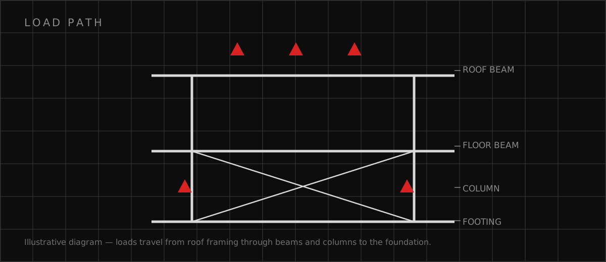
The difference between glancing at drawings and reading them is asking the load path question continuously: how does the load get from here to the ground? Trace a floor load through the joist to the beam, the beam to the column, the column to the footing, the footing to the soil. Then trace the lateral loads: wind on the wall to the diaphragm, diaphragm to the shear wall or frame, frame to the foundation. Anywhere the path is unclear on the drawings is either a detail you haven't found yet or a gap worth asking the engineer about. Check coordination as you go: do the structural openings align with the mechanical ductwork, do the anchor bolt layouts match the steel base plates, do the foundation depths work with the plumbing inverts? Most field problems are coordination problems, and they're visible on the drawings to a reader who's looking. Reading structural drawings well isn't about memorizing symbols — it's about following the forces and questioning the gaps.
- General notes first — design criteria, materials, and abbreviations govern the set
- Plans show layout; sections show stacking; details show connections
- Grid system and schedules locate and size every member
- Trace load paths continuously: gravity down, lateral across and down
- Details reveal design quality — vague details mean unfinished engineering
Which related engineering resources can help?
What else do project teams ask?
What do the abbreviations on structural drawings mean?
What's the difference between a plan, a section, and a detail?
How do I find a specific member on the drawings?
What should I send for an initial review?
Ready to discuss your engineering scope?
Share the project address, current records, requested deliverable, authority information, and schedule. Apex Grid confirms professional responsibility, availability, and scope before work begins.
Request a Project Review