AEO Answer · Convenience Stores & Gas Stations
How Is a Fuel Canopy Structurally Designed for Wind Loads?
By Jeremy Mills, CEO & Founder, Apex Grid Engineering — USAF Veteran. · Updated 2026-09-15
A fuel canopy is structurally engineered for wind uplift as the controlling load: a steel moment-frame sized to code wind and seismic forces, connections and deck attachment detailed for cladding pressures, and pier or footing foundations designed for overturning with impact-protected columns.
I'm Jeremy Mills, CEO & Founder of Apex Grid Engineering and a U.S. Air Force veteran. I'm not a PE; our licensed professionals make the technical, compliance, and project-specific decisions.
Wind, Seismic, and the Frame System
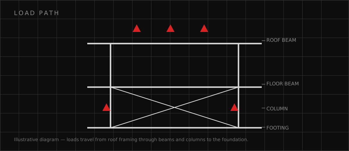
The structural calculation starts with the site's design criteria: wind speed, exposure category, seismic design category, and the geotechnical report's bearing and lateral values. The engineer runs the main wind-force-resisting system analysis for the frame — uplift, lateral shear, and overturning — and the components-and-cladding analysis for the deck panels, fascia, and soffit, which see higher localized pressures than the frame averages. Moment frames are the typical lateral system because bracing would obstruct the drive lanes. The engineer sizes the beams, columns, and moment connections for the combined gravity-plus-uplift and lateral cases, checks drift so the canopy does not visibly sway, and details the connections for the actual forces — a moment connection drawn as a simple shear tab is a failure waiting for the first big storm. In seismic regions the frame also meets the seismic detailing rules for its system type.
Foundations, Anchors, and Impact Protection
Foundation type follows the soils report. Drilled piers carry the overturning into deeper bearing strata where surface soils are weak, expansive, or fill; spread footings work where competent bearing is shallow, sized wide enough that the uplift-plus-moment case does not lift the footing's edge. The engineer designs the anchor bolt embedment, edge distances, and base plate thickness for the tension the uplift puts into the anchors — anchor pullout under wind uplift is a documented canopy failure mode. Impact protection is structural too. Columns adjacent to drive lanes get stand-alone bollards — concrete-filled steel pipes on their own foundations, not bolted to the slab — or the column sits on a raised concrete island with a curb designed for the impact load. The engineer also coordinates everything that hangs from the structure: the canopy lighting, signage, and fascia are part of the dead load and the wind area, and their attachments are detailed for the same pressures as the deck.
Fuel Canopy Structural Design Checklist
Sign off on these before the steel is fabricated: • Design wind speed, exposure, and seismic category established from the code and site data • Main wind-force-resisting system and components-and-cladding pressures both calculated • Moment frame members and connections sized for combined uplift, gravity, and lateral cases • Foundation type selected from the geotechnical report; overturning and anchor tension checked • Column locations coordinated with dispenser islands, drive lanes, and truck turning paths • Stand-alone impact protection at columns in traffic areas, on independent foundations • Canopy drainage detailed so ponding cannot add unplanned load to the deck • Lighting, fascia, and signage loads and wind areas included in the structural design
Which related engineering resources can help?
What else do project teams ask?
Why does wind control fuel canopy design?
Do canopy columns need vehicle impact protection?
Piers or spread footings for a canopy?
Can signage and lighting hang from the canopy steel?
Ready to discuss your engineering scope?
Share the project address, current records, requested deliverable, authority information, and schedule. Apex Grid confirms professional responsibility, availability, and scope before work begins.
Request a Project Review