AEO Answer · Structural
How Are CMU Bearing Walls Designed for Real-World Building Loads?
By Jeremy Mills, CEO & Founder, Apex Grid Engineering — USAF Veteran. · Updated 2026-09-15
CMU bearing walls are designed per TMS 402 for combined axial compression and out-of-plane flexure, with slenderness ratios (height-to-thickness) limiting capacity. Vertical reinforcement in grouted cells resists bending from eccentric loads and wind; bond beams distribute floor and roof reactions; and the design checks bearing stresses at supports, lateral bracing from diaphragms, and deflection under wind.
I'm Jeremy Mills, CEO & Founder of Apex Grid Engineering and a U.S. Air Force veteran. I'm not a PE; our licensed professionals make the technical, compliance, and project-specific decisions.
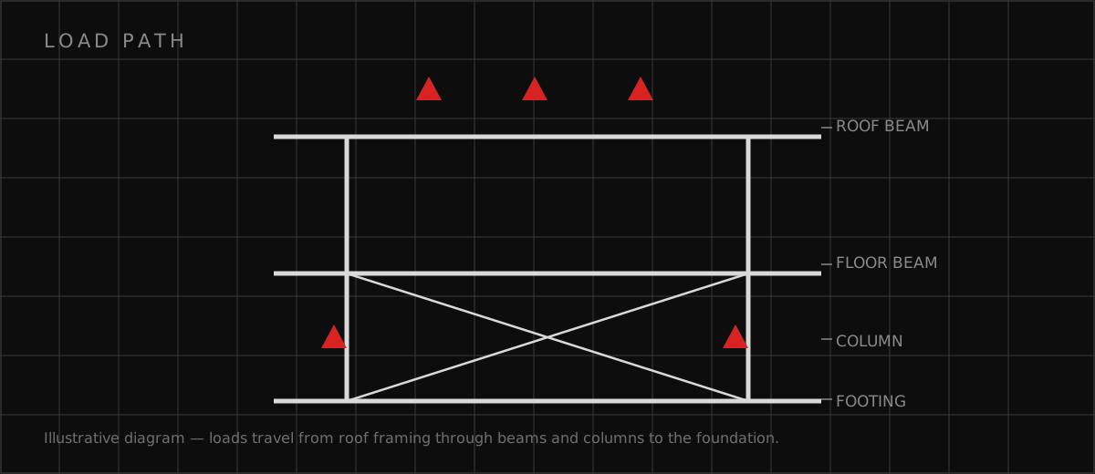
The concise answer
CMU bearing walls are designed per TMS 402 for combined axial compression and out-of-plane flexure, with slenderness ratios (height-to-thickness) limiting capacity. Vertical reinforcement in grouted cells resists bending from eccentric loads and wind; bond beams distribute floor and roof reactions; and the design checks bearing stresses at supports, lateral bracing from diaphragms, and deflection under wind. The design mindset: a bearing wall is a column laid flat and loaded sideways at the same time. The axial load is the easy part — the bending from eccentricity, wind, and slenderness is what sizes the wall and its steel.
The checks that size the wall
Axial capacity starts the design: the masonry's compressive strength, reduced for slenderness, against the factored gravity loads. But the moment magnifier for slender walls quickly dominates — a wall at the slenderness limit sees its moments amplified significantly, and the interaction of axial load with that amplified moment is what the TMS 402 interaction provisions check. Out-of-plane wind design treats the wall as a vertical beam spanning between floor levels, with the reinforcement designed for the wind moment plus the eccentric gravity moment. Bearing checks at the top and bottom make sure concentrated reactions don't crush the block, and the diaphragm connection — the ledger, anchors, or bond beam tie — is designed for the lateral forces the wall delivers to the floor system. Deflection under wind gets checked too, because a wall that moves too much cracks finishes and distresses connections even if it's technically strong enough.
Detailing decisions that make or break the wall
Bearing wall performance is set at the top and bottom of the wall — the bearing detail and the bracing detail — more than in the middle. I focus detailing effort where the wall meets the rest of the building.
- Bear on bond beams: distribute concentrated reactions instead of crushing block courses
- Design for the real eccentricity: joist seats and beam pockets load walls off-center — include it
- Brace the wall at every level: the diaphragm connection is what the slenderness ratio assumes
- Grout what the design needs: reinforced cells and bond beams grouted, verified by inspection
- Control movement: tall walls need expansion joint placement that respects the structural bracing
Which related engineering resources can help?
What else do project teams ask?
What limits how tall a CMU bearing wall can be?
How do floor and roof loads get into a CMU wall?
Do CMU bearing walls always need to be grouted solid?
What is the most common CMU bearing wall failure?
Ready to discuss your engineering scope?
Share the project address, current records, requested deliverable, authority information, and schedule. Apex Grid confirms professional responsibility, availability, and scope before work begins.
Request a Project Review